Viewer
If you have completed the Hello World section. You probably have used the viewer already. In this section we explain how to use the GUI of the viewer.
Free Camera
Control
Use the following keys to move the free camera around:
w move forward.s move backward.a move to the left.d move to the right.Press the Right Mouse Button and drag in the scene to rotate the camera.
Press the Middle Mouse Button and drag in the scene to translate the camera.
This allows moving the camera up and down.
All the operations above will be slower if Shift key is pressed. The speed
can also be changed in the Control Window described below.
Actor Selection
Aim the mouse cursor at an actor in the scene and press Left Mouse Button to
select it. The selected actor should become translucent and a set of coordinate
axes will be placed at the origin of this actor. If the selected actor is an
articulation link with a revolute parent joint, a magenta line will appear to
indicate the rotation axis. For prismatic parent joint, a cyan line will show
the translation axis.
Information of the selected actor will be displayed in the Actor Window
described in detail below. The figure below shows selecting an actor without a
movable parent joint and an actor with a parent revolute joint.


Focused Camera Control
Press f when an actor is selected will enter the Focused Camera Control
mode. In this mode, the center of the camera will be “focused” on the selected
object. In this mode, the Right Mouse Button rotates around the object
instead of object center. Additionally the Mouse Wheel can be used to zoom
in and out. The Shift key can still be used to slow down the camera
movement. Pressing any of wasd will put you back into the Free Camera
Control.
Control Window
The control window (shown below) by default appears at the top-left of the GUI.
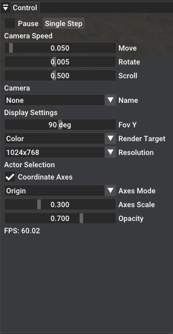
The Pause checkbox, when checked, will pause the simulation (entering a
infinite rendering loop). You can still move the viewer camera around and even
change the pose of objects (details in later sections). The Single Step
button let you jump out of the rendering loop for once.
The Camera Speed section allows you to adjust the speed for various mouse
operations. Move slides adjusts movement speed of wasd. Rotate
adjust the rotating speed when pressing down Right Mouse Button. Scroll
adjusts the zoom speed in Focus Camera Control.
The Name selection in Camera section allows viewing from mounted cameras in the scene. It will
follow the movement of the selected mounted camera.
The Display Settings section allows adjusting some display settings. Fov
Y changes the FOV of the viewer camera. Render Target changes the
displayed texture (texture names are specified in the GLSL shaders provided by
SAPIEN). Resolution changes the window resolution (note this may not always
succeed as window manager can override this setting, for example, it has no
effect in full-screen mode).
The Actor Selection section adjust actor selection behavior. Coordinate
Axes checkbox can turn off the axes display. Axes Mode allows to place
coordinate axes at actor origin or actor center of mass. Axes Scale adjusts
the size of the axes. Opacity adjusts the opacity of the selected actor.
Finally FPS displays the current rendering FPS.
Scene Hierarchy Window
The Scene Hierarchy Window by default is located at the bottom-left corner
of the GUI. It displays information about actors and articulations the scene.

By expanding the scene hierarchy, you can inspect all actors and articulation
links in currently placed in the scene. The currently selected actor will be
highlighted. Left Click on any actor will select it as if it is clicked in
the scene viewport. This allows you to select actors without a visual body.
Actor Window
The Actor Window by default is located at the top-right corner of the GUI.
It displays information about the selected actor.

Actor Window first displays the actor Name, Type, Id. Next the
global position and rotation (quaternion wxyz) are shown.
The Show, Hide collision buttons allows to display collision shapes.
Primitive shapes are displayed in blue while convex meshes are displayed in
green.
Next the expandable Collision Shapes shows the collision shapes attached to
this actor in detail. Depending on the collision type, you can see its
type-specific information such as radius or scale. Some common attributes are
the following. Contact offset the maximum distance where the shape will come
into contact with other shapes. Rest offset the distance where the shape
will collide with other objects (usually 0). Patch radius and Min patch
radius are related to the torsional friction of contact points. Is trigger
indicates whether this shape is a trigger shape. Trigger shape will not collide
with other objects but can report when it intersects with other shapes. Static
friction and Dynamic friction are the friction coefficients.
Restitution is the restitution coefficient of this shape. Next 4 collision
groups are shown in hexadecimal. Next the collision shape’s pose relative to the
actor is displayed.
Articulation Window
The Articulation Window by default is located at the bottom-right corner of
the GUI. It displays information about the parent articulation of selected actor.

First, the Name, Type and Base Link Id of the articulation are
displayed. Next in the expandable section Joints. The joint position and
joint name for each joint is displayed. On the right of the joint names, there
are some arrows to allow further expand each joint. When expanded, you can
change the Drive Target, Damping, Stiffness, Force Limit, and
Friction of this joint. Simply type in the desired number and press
Enter. The Acceleration checkbox indicates whether this joint is driven
by force or acceleration. When driven by acceleration, the drive force scales
automatically by the mass and inertia of the driven object. Finally, the
Show, Hide collision buttons are a convenient way to see the collision
shapes for the entire articulation.
Move Objects
When any object is selected, you may press g to enter Grab Mode or r
to enter Rotate Mode. These functions are analogous to the blender g and
r features. Basically these allows you to move and rotate objects with mouse
move. To gain finer control, you may additionally press x, y, or z
to translate/rotate around a specific axis. For example, g-x will only let
you move in the global x axis. Next if x is pressed twice (g-x-x),
it will only let you move in the local x axis. For grab, if Shift is
pressed when pressing the axis button, you will enter a plane move mode. For
example, g-X allows you to move in the global YZ plane. g-X-X allows you
to move in the local YZ plane.
For this functionality, trying it out will probably be easier than reading this tutorial.